


FR-S2 Series AC Servo Drive
■ Automatically measure the mechanical characteristics of the load inertia, set the optimal gain, and shorten the system debugging time.
Servo Drive Name Rules

|
① |
Driver Series |
FR: AC drive series DR: DC drive series |
|
② |
Drive Type |
S2: Universal type |
|
③ |
Driver Output Power |
01: 100W 04: 400W 07: 750W 10: 1KW 13: 1.3KW 15: 1.5KW 20: 2KW 26: 2.6KW |
|
④ |
Encoder Specifications |
B: 17bit-inc, 17bit-abs C: 23bit-inc, 23bit-abs |
|
⑤ |
Power Voltage |
None: Single-phase 220V 1: Three-phase 220V 2: DC Power Supply 3: Three-phase 380V |
|
⑥ |
Control Model |
None: Pulse Analog Mode EC: EtherCAT Mode |
|
⑦ |
Special Order Products |
***: Customized products |
Specification Introduction
|
Input Power Supply |
Single-phase/Three-phase AC220V ±10% 50-60Hz |
|
|
Encoder Type |
1. Optical encoding and magnetic encoding: 17-bit encoder, 23-bit encoder |
|
|
Control Method |
0: Position Control method 1: Speed Control Method 2: Torque Control Method |
|
|
Protective Function |
Overspeed, main power overvoltage/undervoltage, overcurrent, overload, encoder abnormality, control power abnormality, position deviation, etc |
|
|
Monitoring Function |
Speed, current position, command pulse accumulation, position deviation, motor torque, motor current, running status, etc. |
|
|
Regenerative resistor |
Internal regenerative resistor or external regenerative resistor (optional) |
|
|
Control Characteristics |
Speed Frequency Response |
≥500Hz |
|
Speed Change Rate |
<±0.01%(load fluctuation 0~100%); <±10% (rated voltage±10%) (the value corresponds to the rated speed) |
|
|
Speed Control Range |
1: 10000 (the lower limit of the speed control range is stable operation without crawling under rated load) |
|
|
Position Control |
Pulse Frequency |
≤6M (differential mode); ≤500K (single-ended mode) |
|
Input Method |
1. Pulse + sign 2. CW pulse + CCW pulse 3. Positive and negative AB phase pulse |
|
|
Electronic Gear Ratio |
A/B (A=0~65535, B=1~65535) |
|
|
Speed Control
|
Speed Command Input Method |
External analog quantity, internal speed command |
|
External Analog Command Voltage |
The maximum input voltage is ± 10V The variable setting range is 0~±10Vdc/0~±6000rpm. |
|
|
Torque Control |
Command Voltage |
Maximum input voltage: ±10V (positive voltage corresponds to positive torque) Factory default setting: 3.3VDC corresponds to rated torque |
|
Electrical Time Constant |
47μs |
|
|
Input Resistance |
About 20KΩ |
|
|
Display and Operation |
5-digit LED digital display, 4 buttons |
|
|
Usage Environment |
Working temperature: 0~55℃, storage temperature: -20~80℃ Humidity: <90% (no condensation) |
|
Wiring Diagram

Air Circuit Breaker
Used to protect the power line and cut off the circuit when there is overcurrent
Noise Filter
Used to prevent noise from outside the cable
Electromagnetic Contactor
Turn on/off the servo power supply and install an AC surge suppressor when in use
Braking Resistor
The default built-in braking resistor, when the bus capacitance is insufficient, the P-C terminal is connected to an external braking resistor
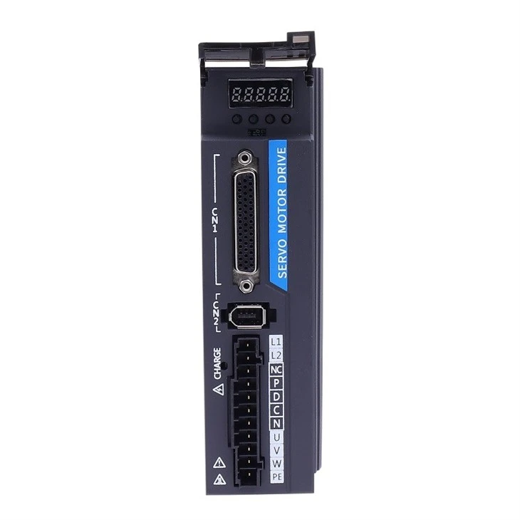
Servo drive front panel introduction

|
Number |
Terminal Name |
Function Description |
|
① |
CN3,CN4 |
Communication terminals. |
|
② |
CN1 |
Input and output control signal terminals. |
|
③ |
CN2 |
Encoder signal terminal, connected to motor encoder. |
|
④ |
L1,L2 |
Main power input terminal. |
|
⑤ |
CHARGE |
Bus voltage indicator light. Used to indicate that the bus capacitor is in a charged state. When the indicator light is on, even if the main circuit power is turned off, the internal capacitor of the servo unit may still have charge. Therefore, do not touch the power terminal when the light is on to avoid electric shock. |
|
⑥ |
P,D,C,N |
Brake resistor connection terminal. |
|
⑦ |
U,V,W |
Servo motor connection terminal. Connect servo motors U, V, and W phases. |
|
⑧ |
PE |
Grounding terminal. Connect to the power supply and motor grounding terminals for grounding treatment. |
Specification and Model
|
Drive Model |
FR-S2-01B |
FR-S2-02B |
FR-S2-04B |
FR-S2-07B |
FR-S2-10B |
|
Power |
100W |
200W |
400W |
750W |
1000W |
|
Drive Model |
FR-S2-13B |
FR-S2-15B |
FR-S2-18B |
FR-S2-20B |
FR-S2-26B |
|
Power |
1.3KW |
1.5KW |
1.8KW |
2.0KW |
2.6KW |
Servo Driver Terminal Pin Distribution

▲The above figures all show the pin arrangement of the terminals of the driver body.
CN1 Control Signal Terminal
CN1 control signal terminal provides signals needed for connection with upper controller, using DB44 socket, and signals include:
◆ 4 programmable inputs
◆ 4 programmable outputs
◆ Analog instruction input
◆ Command pulse input

◆ It is recommended to use 24-26AWG cable.

Features
■ Adopt the latest DSP, CPLD and intelligent power module, with high precision and good reliability.
■ Automatically measure the mechanical characteristics of the load inertia, set the optimal gain, and shorten the system debugging time.
■ Friction torque compensation function can reduce the influence of static friction during mechanical commutation and improve the command following performance of low-speed operation.
■ Small size, new concept appearance design, beautiful and elegant.
■ Support load disturbance observer, which can perform torque feed-forward compensation and improve the dynamic response of the system.
■ With bus voltage compensation function, wide power supply range.
■ With multiple protection and alarm functions, over-current, over-voltage, over-heat and encoder failure.
■ PC debugging software support, can carry out functions such as mechanical characteristic analysis, parameter setting, etc., and the operation is intuitive and simple.
Hot Tags: fr-s2 series ac servo drive, China fr-s2 series ac servo drive manufacturers, factory, Servo Driver, FR S2 Series AC Servo Drive
Previous
No InformationNext
No InformationYou Might Also Like


Send Inquiry